Within a combined tracking area updating procedure the messages TRACKING AREA UPDATE ACCEPT and TRACKING AREA UPDATE COMPLETE carry information for the tracking area updating and the location area updating.
The UE operating in CS/PS mode 1 or CS/PS mode 2, in state EMM-REGISTERED, shall initiate the combined tracking area updating procedure:
a) when the UE that is attached for both EPS and non-EPS services detects entering a tracking area that is not in the list of tracking areas that the UE previously registered in the MME;
b) when the UE that is attached for EPS services wants to perform an attach for non-EPS services. In this case the EPS update type IE shall be set to "combined TA/LA updating with IMSI attach";
c) when the UE performs an intersystem change from A/Gb mode to S1 mode and the EPS services were previously suspended in A/Gb mode;
d) when the UE performs an intersystem change from A/Gb or Iu mode to S1 mode and the UE previously performed a location area update procedure or a combined routing area update procedure in A/Gb or Iu mode, in order to re-establish the SGs association. In this case the EPS update type IE shall be set to "combined TA/LA updating with IMSI attach";
e) when the UE enters EMM-REGISTERED.NORMAL-SERVICE and the UE's TIN indicates "P-TMSI";
f) when the UE receives an indication from the lower layers that the RRC connection was released with cause "load balancing TAU required";
g) when the UE deactivated EPS bearer context(s) locally while in EMM-REGISTERED.NO-CELL-AVAILABLE, and then returns to EMM-REGISTERED.NORMAL-SERVICE;
h) when the UE changes the UE network capability information or the MS network capability information or both;
i) when the UE changes the UE specific DRX parameter;
j) when the UE receives an indication of "RRC Connection failure" from the lower layers and has no user uplink data pending;
k) when due to manual CSG selection the UE has selected a CSG cell whose CSG identity is not included in the UE's Allowed CSG list;
l) when the UE reselects an E-UTRAN cell while it was in GPRS READY state or PMM-CONNECTED mode;
m) when the UE supports SRVCC to GERAN or UTRAN and changes the mobile station classmark 2 or the supported codecs, or the UE supports SRVCC to GERAN and changes the mobile station classmark 3; or
n) when the UE changes the radio capability of at least one of the following radio access technologies: GERAN, UTRAN or cdma2000®.
For case n, the UE shall include a UE radio capability information update needed IE in the TRACKING AREA UPDATE REQUEST message.
Tuesday, February 23, 2010
Monday, February 22, 2010
Tracking Area Update (TAU) Procedure Initiation
The UE in state EMM-REGISTERED shall initiate the tracking area updating procedure by sending a TRACKING AREA UPDATE REQUEST (TAU) message to the MME,
a) when the UE detects entering a tracking area that is not in the list of tracking areas that the UE previously registered in the MME;
b) when the periodic tracking area updating timer T3412 expires;
c) when the UE enters EMM-REGISTERED.NORMAL-SERVICE and the UE's TIN indicates "P-TMSI";
d) when the UE performs an inter-system change from S101 mode to S1 mode and has no user data pending;
e) when the UE receives an indication from the lower layers that the RRC connection was released with cause "load balancing TAU required";
f) when the UE deactivated EPS bearer context(s) locally while in EMM-REGISTERED.NO-CELL-AVAILABLE, and then returns to EMM-REGISTERED.NORMAL-SERVICE;
g) when the UE changes the UE network capability information or the MS network capability information or both;
h) when the UE changes the UE specific DRX parameter;
i) when the UE receives an indication of "RRC Connection failure" from the lower layers and has no user uplink data pending;
j) when the UE enters S1 mode after 1xCS fallback;
k) when due to manual CSG selection the UE has selected a CSG cell whose CSG identity is not included in the UE's Allowed CSG list;
l) when the UE reselects an E-UTRAN cell while it was in GPRS READY state or PMM-CONNECTED mode;
m) when the UE supports SRVCC to GERAN or UTRAN and changes the mobile station classmark 2 or the supported codecs, or the UE supports SRVCC to GERAN and changes the mobile station classmark 3; or
n) when the UE changes the radio capability of at least one of the following radio access technologies: GERAN, UTRAN or cdma2000®.
For all cases except case b, the UE shall set the EPS update type IE to "TA updating". For case b, the UE shall set the EPS update type IE to "periodic updating".
For case n, the UE shall include a UE radio capability information update needed IE in the TRACKING AREA UPDATE REQUEST message.
Sunday, February 7, 2010
Logical Channels
- Control Channels
- Broadcast Control Channel (BCCH)
A downlink channel for broadcasting system control information. - Paging Control Channel (PCCH)
A downlink channel that transfers paging information and system information change notifications. This channel is used for paging when the network does not know the location cell of the UE. - Common Control Channel (CCCH)
Channel for transmitting control information between UEs and network. This channel is used for UEs having no RRC connection with the network. - Multicast Control Channel (MCCH)
A point-to-multipoint downlink channel used for transmitting MBMS control information from the network to the UE, for one or several MTCHs. This channel is only used by UEs that receive MBMS. - Dedicated Control Channel (DCCH)
A point-to-point bi-directional channel that transmits dedicated control information between a UE and the network. Used by UEs having an RRC connection.
- Traffic Channels
Traffic channels are used for the transfer of user plane information only. The traffic channels offered by MAC are:
- Dedicated Traffic Channel (DTCH)
A Dedicated Traffic Channel (DTCH) is a point-to-point channel, dedicated to one UE, for the transfer of user information. A DTCH can exist in both uplink and downlink. - Multicast Traffic Channel (MTCH)
A point-to-multipoint downlink channel for transmitting traffic data from the network to the UE. This channel is only used by UEs that receive MBMS.
Friday, February 5, 2010
Transport Channels in LTE
The physical layer offers information transfer services to MAC and higher layers. The physical layer transport services are described by how and with what characteristics data are transferred over the radio interface.
Downlink transport channel types are:
1. Broadcast Channel (BCH) characterised by:
1. Uplink Shared Channel (UL-SCH) characterised by:
Downlink transport channel types are:
1. Broadcast Channel (BCH) characterised by:
- fixed, pre-defined transport format;
- requirement to be broadcast in the entire coverage area of the cell.
- support for HARQ;
- support for dynamic link adaptation by varying the modulation, coding and transmit power;
- possibility to be broadcast in the entire cell;
- possibility to use beam forming;
- support for both dynamic and semi-static resource allocation;
- support for UE discontinuous reception (DRX) to enable UE power saving;
- support for UE discontinuous reception (DRX) to enable UE power saving (DRX cycle is indicated by the network to the UE);
- requirement to be broadcast in the entire coverage area of the cell;
- mapped to physical resources which can be used dynamically also for traffic/other control channels.
- requirement to be broadcast in the entire coverage area of the cell;
- support for MBSFN combining of MBMS transmission on multiple cells;
- support for semi-static resource allocation e.g. with a time frame of a long cyclic prefix.
1. Uplink Shared Channel (UL-SCH) characterised by:
- possibility to use beamforming; (likely no impact on specifications)
- support for dynamic link adaptation by varying the transmit power and potentially modulation and coding;
- support for HARQ;
- support for both dynamic and semi-static resource allocation.
- limited control information;
- collision risk;
Thursday, February 4, 2010
Paging in LTE
The paging procedure is used by the network to request the establishment of a NAS signalling connection to the UE. The NAS signalling connection thus established can also be used to transport cdma2000® signalling messages to the UE. Another purpose of the paging procedure is to prompt the UE to reattach if necessary as a result of a network failure. If the UE is not attached when it receives a paging for EPS services, the UE shall ignore the paging. Additionally, the network can use the paging procedure to initiate the mobile terminating CS fallback procedure.
- Paging for EPS services through E-UTRAN using S-TMSI
The network shall initiate the paging procedure for EPS services using S-TMSI with CN domain indicator set to "PS" when NAS signalling messages, cdma2000® signalling messages or user data is pending to be sent to the UE when no NAS signalling connection exists. Upon reception of a paging indication, the UE responds to the paging with a SERVICE REQUEST message.

- Paging for EPS services through E-UTRAN using IMSI
Paging for EPS services using IMSI is an abnormal procedure used for error recovery in the network. The network may initiate paging for EPS services using IMSI with CN domain indicator set to "PS" if the S-TMSI is not available due to a network failure.

Upon reception of a paging for EPS services using IMSI, the UE shall locally deactivate any EPS bearer context(s) and locally detach from EPS. Additionally the UE shall delete the following parameters: last visited registered TAI, TAI list, GUTI and KSIASME. The UE shall set the EPS update status to EU2 NOT UPDATED and change the state to EMM-DEREGISTERED.
After performing the local detach, the UE shall then perform an attach procedure. If the UE is operating in CS/PS mode 1 or CS/PS mode 2 of operation, then the UE shall perform a combined attach procedure.
-Paging for CS fallback to A/Gb or Iu mode
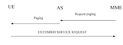
The network may initiate the paging procedure for non-EPS services when the UE is IMSI attached for non-EPS services. To initiate the procedure when no NAS signalling connection exists, the EMM entity in the network requests the lower layer to start paging. The paging message includes a CN domain indicator set to "CS" in order to indicate that this is paging for CS fallback.
To notify the UE about an incoming mobile terminating CS service when a NAS signalling connection exists, the EMM entity in the network shall send a CS SERVICE NOTIFICATION message. This message may also include CS service related parameters (e.g. Calling Line Identification, SS or LCS related parameters).
Upon reception of a paging indication, the UE shall respond with an EXTENDED SERVICE REQUEST. If the paging is received in EMM-IDLE mode, the UE shall respond immediately. If the paging is received as NAS CS NOTIFICATION message in EMM-CONNECTED mode, the UE may request upper layers input i.e. to accept or reject CS fallback before responding with an EXTENDED SERVICE REQUEST. The response is indicated in the CSFB response information element in the EXTENDED SERVICE REQUEST message in both EMM-IDLE and EMM-CONNECTED modes.
- Paging for EPS services through E-UTRAN using S-TMSI
The network shall initiate the paging procedure for EPS services using S-TMSI with CN domain indicator set to "PS" when NAS signalling messages, cdma2000® signalling messages or user data is pending to be sent to the UE when no NAS signalling connection exists. Upon reception of a paging indication, the UE responds to the paging with a SERVICE REQUEST message.

- Paging for EPS services through E-UTRAN using IMSI
Paging for EPS services using IMSI is an abnormal procedure used for error recovery in the network. The network may initiate paging for EPS services using IMSI with CN domain indicator set to "PS" if the S-TMSI is not available due to a network failure.

Upon reception of a paging for EPS services using IMSI, the UE shall locally deactivate any EPS bearer context(s) and locally detach from EPS. Additionally the UE shall delete the following parameters: last visited registered TAI, TAI list, GUTI and KSIASME. The UE shall set the EPS update status to EU2 NOT UPDATED and change the state to EMM-DEREGISTERED.
After performing the local detach, the UE shall then perform an attach procedure. If the UE is operating in CS/PS mode 1 or CS/PS mode 2 of operation, then the UE shall perform a combined attach procedure.
-Paging for CS fallback to A/Gb or Iu mode
The network may initiate the paging procedure for non-EPS services when the UE is IMSI attached for non-EPS services. To initiate the procedure when no NAS signalling connection exists, the EMM entity in the network requests the lower layer to start paging. The paging message includes a CN domain indicator set to "CS" in order to indicate that this is paging for CS fallback.
To notify the UE about an incoming mobile terminating CS service when a NAS signalling connection exists, the EMM entity in the network shall send a CS SERVICE NOTIFICATION message. This message may also include CS service related parameters (e.g. Calling Line Identification, SS or LCS related parameters).
Upon reception of a paging indication, the UE shall respond with an EXTENDED SERVICE REQUEST. If the paging is received in EMM-IDLE mode, the UE shall respond immediately. If the paging is received as NAS CS NOTIFICATION message in EMM-CONNECTED mode, the UE may request upper layers input i.e. to accept or reject CS fallback before responding with an EXTENDED SERVICE REQUEST. The response is indicated in the CSFB response information element in the EXTENDED SERVICE REQUEST message in both EMM-IDLE and EMM-CONNECTED modes.

Subscribe to:
Posts (Atom)