Friday, November 12, 2010

NAS Service request procedure

This procedure is one of the EMM connection management procedures. The purpose of the service request procedure is to transfer the EMM mode from EMM-IDLE to EMM-CONNECTED mode and establish the radio and S1 bearers when uplink user data or signalling is to be sent. Another purpose of this procedure is to invoke MO(mobile Originated/MT(Mobile Terminated) CS fallback procedures.

This procedure is used when:

- the network has downlink signalling pending;
- the UE has uplink signalling pending;
- the UE or the network has user data pending and the UE is in EMM-IDLE mode;

- the UE in EMM-IDLE or EMM-CONNECTED mode has requested to perform mobile originating/terminating CS fallback;
- the network has downlink cdma2000® signalling pending; or
- the UE has uplink cdma2000® signalling pending.

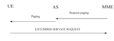
The service request procedure is initiated by the UE, however, for the downlink transfer of signalling, cdma2000® signalling or user data in EMM-IDLE mode, the trigger is given by the network by means of the paging procedure.

The UE invokes the service request procedure when:

a) the UE in EMM-IDLE mode receives a paging request with CN domain indicator set to "PS" from the network;

b) the UE, in EMM-IDLE mode, has pending user data to be sent;

c) the UE, in EMM-IDLE mode, has uplink signalling pending;

d) the UE in EMM-IDLE or EMM-CONNECTED mode is configured to use CS fallback and has a mobile originating CS fallback request from the upper layer;

e) the UE in EMM-IDLE mode is configured to use CS fallback and receives a paging request with CN domain indicator set to "CS", or the UE in EMM-CONNECTED mode is configured to use CS fallback and receives a CS SERVICE NOTIFICATION message;

f) the UE in EMM-IDLE or EMM-CONNECTED mode is configured to use 1xCS fallback and has a mobile originating 1xCS fallback request from the upper layer;

g) the UE in EMM-CONNECTED mode is configured to use 1xCS fallback and accepts cdma2000® signalling messages containing a 1xCS paging request; or

h) the UE, in EMM-IDLE mode, has uplink cdma2000® signalling pending.

If one of the above criteria to invoke the service request procedure is fulfilled, then the service request procedure may only be initiated by the UE when the following conditions are fulfilled:

- its EPS update status is EU1 UPDATED, and the TAI of the current serving cell is included in the TAI list; and

- no EMM specific procedure is ongoing.

If the UE has pending uplink data or uplink signalling in EMM-IDLE mode to be transmitted or it responds to paging with CN domain indicator set to "PS", the UE initiates the service request procedure by sending a SERVICE REQUEST message to the MME, and enters the state EMM-SERVICE-REQUEST-INITIATED.

For case d, the UE shall send an EXTENDED SERVICE REQUEST message, start T3417ext and enter the state EMM-SERVICE-REQUEST-INITIATED.

For case e:

- if the UE is in EMM-IDLE mode, the UE shall send an EXTENDED SERVICE REQUEST message, and enter the state EMM-SERVICE-REQUEST-INITIATED;

- if the UE is in EMM-CONNECTED mode and if the UE accepts the paging, the UE shall send an EXTENDED SERVICE REQUEST message with the CSFB response IE indicating "CS fallback accepted by the UE", and enter the state EMM-SERVICE-REQUEST-INITIATED;

- if the UE is in EMM-CONNECTED mode and if the UE rejects the paging, the UE shall send an EXTENDED SERVICE REQUEST message with the CSFB response IE indicating "CS fallback rejected by the UE" and enter the state EMM-REGISTERED.NORMAL-SERVICE. The network should not initiate CS fallback procedures.

For cases f and g, the UE shall send an EXTENDED SERVICE REQUEST message, and enter the state EMM-SERVICE-REQUEST-INITIATED.

Sunday, October 24, 2010

LTE Layer 1 Services

Multiple Access
The multiple access scheme for the LTE physical layer is based on Orthogonal Frequency Division Multiplexing (OFDM) with a cyclic prefix (CP) in the downlink, and on Single-Carrier Frequency Division Multiple Access (SC-FDMA) with a cyclic prefix in the uplink. To support transmission in paired and unpaired spectrum, two duplex modes are supported: Frequency Division Duplex (FDD), supporting full duplex and half duplex operation, and Time Division Duplex (TDD).

The Layer 1 is defined in a bandwidth agnostic way based on resource blocks, allowing the LTE Layer 1 to adapt to various spectrum allocations. A resource block spans either 12 sub-carriers with a sub-carrier bandwidth of 15kHz or 24 sub-carriers with a sub-carrier bandwidth of 7.5kHz each over a slot duration of 0.5ms.

The radio frame structure type 1 is used for FDD (for both full duplex and half duplex operation) and has a duration of 10ms and consists of 20 slots with a slot duration of 0.5ms. Two adjacent slots form one sub-frame of length 1ms. The radio frame structure type 2 is used for TDD and consists of two half-frames with a duration of 5ms each and containing each 8 slots of length 0.5ms and three special fields (DwPTS, GP and UpPTS) which have configurable individual lengths and a total length of 1ms.

A sub-frame consists of two adjacent slots, except for sub-frames 1 and 6, which consist of DwPTS, GP and UpPTS. Both 5ms and 10ms switch-point periodicity are supported.

To support a Multimedia Broadcast and Multicast Service (MBMS), LTE offers the possibility to transmit Multicast/Broadcast over a Single Frequency Network (MBSFN), where a time-synchronized common waveform is transmitted from multiple cells for a given duration. MBSFN transmission enables highly efficient MBMS, allowing for over-the-air combining of multi-cell transmissions in the UE, where the cyclic prefix is utilized to cover the difference in the propagation delays, which makes the MBSFN transmission appear to the UE as a transmission from a single large cell. Transmission on a dedicated carrier for MBSFN with the possibility to use a longer CP with a sub-carrier bandwidth of 7.5kHz is supported as well as transmission of MBSFN on a carrier with both MBMS transmissions and point-to-point transmissions using time division multiplexing.

Transmission with multiple input and multiple output antennas (MIMO) are supported with configurations in the downlink with two or four transmit antennas and two or four receive antennas, which allow for multi-layer transmissions with up to four streams. Multi-user MIMO i.e. allocation of different streams to different users is supported in both UL and DL.

Physical channels and modulation

The physical channels defined in the downlink are:
• the Physical Downlink Shared Channel (PDSCH),
• the Physical Multicast Channel (PMCH),
• the Physical Downlink Control Channel (PDCCH),
• the Physical Broadcast Channel (PBCH),
• the Physical Control Format Indicator Channel (PCFICH)
• and the Physical Hybrid ARQ Indicator Channel (PHICH).

The physical channels defined in the uplink are:
• the Physical Random Access Channel (PRACH),
• the Physical Uplink Shared Channel (PUSCH),
• and the Physical Uplink Control Channel (PUCCH).

In addition, signals are defined as reference signals, primary and secondary synchronization signals. The modulation schemes supported in the downlink and uplink are QPSK, 16QAM and 64QAM.

Channel coding and interleaving
The channel coding scheme for transport blocks in LTE is Turbo Coding with a coding rate of R=1/3, two 8-state constituent encoders and a contention-free quadratic permutation polynomial (QPP) turbo code internal interleaver. Trellis termination is used for the turbo coding. Before the turbo coding, transport blocks are segmented into byte aligned segments with a maximum information block size of 6144 bits. Error detection is supported by the use of 24 bit CRC. 

Physical layer procedures
There are several Physical layer procedures involved with LTE operation. Such procedures covered by the physical layer are;
- Cell search
- Power control
- Uplink synchronisation and Uplink timing control
- Random access related procedures
- HARQ related procedures
Through the control of physical layer resources in the frequency domain as well as in the time and power domain, implicit support of interference coordination is provided in LTE.

Physical layer measurements
Radio characteristics are measured by the UE and the eNode-B and reported to higher layers in the network. These include, e.g. measurements for intra- and inter-frequency handover, inter RAT handover, timing measurements and measurements for RRM and in support for positioning. Measurements for inter-RAT handover are defined in support of handover to GSM, UTRA FDD, UTRA TDD, CDMA2000 1x RTT and CDMA2000 HRPD.

Friday, October 22, 2010

LTE Layer 1

The radio interface is composed of the Layer 1, 2 and 3. Below figure shows the E-UTRA radio interface protocol architecture around the physical layer (Layer 1). The physical layer interfaces the Medium Access Control (MAC) sub-layer of Layer 2 and the Radio Resource Control (RRC) Layer of Layer 3. The circles between different layer/sub-layers indicate Service Access Points (SAPs). The physical layer offers a transport channel to MAC. The transport channel is characterized by how the information is transferred over the radio interface. MAC offers different logical channels to the Radio Link Control (RLC) sub-layer of Layer 2. A logical channel is characterized by the type of information transferred.


Service provided to higher layers

The physical layer offers data transport services to higher layers. The access to these services is through the use of a transport channel via the MAC sub-layer. The physical layer is expected to perform the following functions in order to provide the data transport service:

- Error detection on the transport channel and indication to higher layers
- FEC encoding/decoding of the transport channel
- Hybrid ARQ soft-combining
- Rate matching of the coded transport channel to physical channels
- Mapping of the coded transport channel onto physical channels
- Power weighting of physical channels
- Modulation and demodulation of physical channels
- Frequency and time synchronisation
- Radio characteristics measurements and indication to higher layers
- Multiple Input Multiple Output (MIMO) antenna processing
- Transmit Diversity (TX diversity)
- Beamforming
- RF processing.

Monday, September 20, 2010

SRVCC between LTE and 3GPP2 1xCS

Basics:
  • 1xCS: The 3GPP2 legacy circuit switched signalling system as defined in 3GPP2 X.S0042-0
  • 3GPP SRVCC UE: A 3GPP SRVCC UE is a UE enhanced for IMS Service Continuity with the additional UE capabilities such as SRVCC between E-UTRAN and 3GPP UTRAN and / or between E-UTRAN and 3GPP GERAN and / or between UTRAN (HSPA) and 3GPP UTRAN and 3GPP GERAN.
Concept:

For SRVCC-capable UEs, the call is always anchored at the VCC AS in the 3GPP2's IMS. The 3GPP2 1xCS IWS enables a single radio UE to communicate in parallel both with the source system and the target system. From VCC perspective, this mechanism minimizes the voice gap by supporting the transport of signalling for establishment of the target CS access leg while the terminal is connected to the source PS access network.
Transport of 3GPP2 1xCS signalling messages for preparation of the CS access leg in the target system

The S102 reference point is used to convey 3GPP2 1xCS signalling messages between the MME and 3GPP2 1xCS IWS. These 1x CS signalling messages are actually exchanged between the UE and the 3GPP2 1xCS IWS, and S102 is only one link in the overall UE 1xCS IWS tunnelling path. On the remaining portion of the tunnelling path, the 3GPP2 1xCS signalling messages are encapsulated in E UTRAN/EPS tunnelling messages (UE MME).

E-UTRAN and 3GPP2 1xCS SRVCC architecture


SRVCC architecture for E-UTRAN to 3GPP2 1xCS

Call flows for SRVCC from E-UTRAN

LTE VoIP-to-1x CS voice service continuity
1. Ongoing VoIP session over the IMS access leg established over EPS/E UTRAN access.

2. 1xCS SRVCC UE sends measurement reports to eNodeB.

3. The E UTRAN (e.g., based on some trigger, measurement reports) makes a determination to initiate an inter technology handover to cdma2000 1xRTT.

4. The E UTRAN signals the UE to perform an inter technology handover by sending a Handover from EUTRA Preparation Request message.

5. The UE initiates signalling for establishment of the CS access leg by sending a UL handover preparation Transfer message containing the 1xRTT Origination message. For the case of emergency voice service continuity, the request includes a Request-Type = "emergency handover" and in the case of UE operating in Limited Service Mode the MEID (e.g. IMEI) is included.

6. The E UTRAN sends an Uplink S1 cdma2000 Tunnelling (MEID, RAND, 1x Origination, Reference CellID) message to the MME. The eNodeB will also include CDMA2000 HO Required Indication IE to Uplink S1 CDMA2000 Tunnelling message, which indicates to the MME that the handover preparation has started.

7. Upon reception of the Uplink S1 cdma2000 Tunnelling message, the MME selects a 3GPP2 1xCS IWS based on Reference CellID and encapsulates the 1x Origination Message along with the MEID and RAND in a S102 Direct Transfer message (as "1x Air Interface Signalling").

8. The traffic channel resources are established in the 1x RTT system and 3GPP2 1xCS procedures for initiation of Session Transfer are performed as per 3GPP2 X.S0042 [4].

9. The 3GPP2 1xCS IWS creates a 1x message and encapsulates it in a S102 Direct Transfer message (1x message, Handover indicator). If the 3GPP2 access was able to allocate resources successfully, the 1x message is a 1x Handover Direction message and the handover indicator indicates successful resource allocation. Otherwise, the handover indicator indicates to the MME that handover preparation failed and the embedded 1x message indicates the failure to the UE.

10. The MME sends the 1x message and CDMA2000 HO Status IE in a Downlink S1 cdma2000 Tunnelling message to the E UTRAN. The CDMA2000 HO Status IE is set according to the handover indicator received over the S102 tunnel.

11. If the CDMA2000 HO Status IE indicates successful handover preparation, the E UTRAN forwards the 1x Handoff Direction message embedded in a Mobility from EUTRA Command message to the UE. This is perceived by the UE as a Handover Command message. If handover preparation failed, DL Information transfer message will be sent instead, with the embedded 1xRTT message that indicates the failure to the UE.

12. Once the UE receives the traffic channel information from the cdma2000 1xRTT system, the UE retunes to the 1xRTT radio access network and performs traffic channel acquisition with the 1xRTT CS access (e.g., 1xRTT BSS).

13. The UE sends a 1xRTT handoff completion message to the 1xRTT CS access (e.g., 1xRTT BSS).

14. The 1xRTT CS Access sends message to 1xRTT MSC to indicate of handoff done. The resources between 1x CS IWS and 1xRTT MSC may be released at this step.

15. Ongoing voice call over the CS access leg established over 1xRTT access. The E UTRAN/EPS context may be released based on the normal E UTRAN/EPS procedure.

16. The eNodeB sends an S1 UE Context Release Request (Cause) message to the MME. Cause indicates the S1 release procedure is caused by handover from E-UTRAN to 1xRTT.

17. The MME exchanges Suspend Request/ Acknowledge messages with the S GW / P GW. The S1-U bearers are released for all EPS bearers and the GBR bearers are deactivated by the MME. The non-GBR bearers are preserved and are marked as suspended in the S GW / P GW. Upon receipt of downlink data the S GW should not send a downlink data notification message to the MME.

18. S1 UE Context in the eNodeB is released as specified in TS 23.401 [2].

19. For an emergency services session after handover is complete, if the control plane location solution is used on the source side, the source MME shall send a Subscriber Location Report carrying an indication of the 1xRTT MSC (e.g. reference cell ID) to the GMLC associated with the source side to support location continuity. This enables location continuity for the 1xRTT side. Alternatively, if the control plane solution is not used on the source side, location continuity procedures shall be instigated on the 1xRTT side.

Tuesday, September 7, 2010

Single Radio Voice Call Continuity (SRVCC)

SRVCC is an LTE functionality that allows a VoIP/IMS call in the LTE packet domain to be moved to a legacy voice domain (GSM/UMTS or CDMA 1x).

Consider a case where a new LTE network operator wants to move voice services to VoIP over IMS in conjunction with the deployment of an LTE access network. In the absence of other options, this operator would need to provide ubiquitous LTE coverage on day 1 to have a competitive VoIP service. However SRVCC enabled LTE may not require complete LTE coverage.

SRVCC provides the ability to transition a voice call from the VoIP/IMS packet domain to the legacy circuit domain. Variations of SRVCC are being standardized to support both GSM/UMTS and CDMA 1x circuit domains. For an operator with a legacy cellular network who wishes to deploy IMS/VoIP-based voice services in conjunction with the rollout of an LTE network, SRVCC offers VoIP subscribers with coverage over a much larger area than would typically be available during the rollout of a new network.

SRVCC functions as follows. As an SRVCC-capable UEe engaged in a voice call determines that it is moving away from LTE coverage, it notifies the LTE network. The LTE network determines that the voice call needs to be moved to the legacy circuit domain. It notifies the MSC server of the need to switch the voice call from the packet to the circuit domain and initiates a handover of the LTE voice bearer to the circuit network. The MSC server establishes a bearer path for the mobile in the legacy network and notifies the IMS core that the mobile’s call leg is moving from the packet to the circuit domain. The circuit-packet function in the IMS core then performs the necessary inter-working functions. When the mobile arrives on-channel in the legacy network, it switches its internal voice processing from VoIP to legacy-circuit voice, and the call continues.


If the legacy circuit network also has an associated packet capability and is capable of supporting concurrent circuit/packet operations, the subscriber’s data sessions can be handed over to the legacy network in conjunction with switching the voice call from the packet to the circuit domain. In this case when the voice call finishes and the mobile re-enters LTE coverage, these packet sessions can be handed back to the LTE.

If operators look to limit LTE deployments to high traffic areas and at the same time wish to transition voice service in those areas to VoIP, then SRVCC is exactly what they need.

If on the other hand operators do not plan to migrate their voice service to VoIP, then SRVCC is not for them. If an operator does plan to migrate to VoIP and also plans to roll out ubiquitous LTE coverage, then the question of whether or not to adopt SRVCC is more complicated. While SRVCC does not require modifications to what is certainly the operator’s largest legacy investment, the RAN, it does require a significant modification of the operator’s legacy core and also requires full deployment of IMS circuit-packet continuity services. Given the cost of these changes, deployment of SRVCC purely as an interim measure to allow early rollout of VoIP-based services may not make financial sense.

Source: Motorola's WhitePaper on "LTE Inter-technology Mobility"

Thursday, September 2, 2010

Timing Advance(TA) in LTE

In GSM system MS sends its data three time slots after it received the data from the BTS. This is ok as long as MS-BTS distance is small but increasing distance requires consideration of propagation delay as well. To handle it Timing advance (TA) is conveyed by network to MS and current value is sent to the MS within the layer 1 header of each SACCH. BTS calculates the first TA when it receives RACH and reports it to the BSC and BSC/BTS passes it to UE during Immediate Assignment.

In UMTS Timing Advance parameter was not used but in LTE Timing Advance is back.

In LTE, when UE wish to establish RRC connection with eNB, it transmits a Random Access Preamble, eNB estimates the transmission timing of the terminal based on this. Now eNB transmits a Random Access Response which consists of timing advance command, based on that UE adjusts the terminal transmit timing.

The timing advance is initiated from E-UTRAN with MAC message that implies and adjustment of the timing advance.

3GPP TA Requirements
  • Timing Advance adjustment delay
UE shall adjust the timing of its uplink transmission timing at sub-frame n+6 for a timing advancement command received in sub-frame n.
  • Timing Advance adjustment accuracy
The UE shall adjust the timing of its transmissions with a relative accuracy better than or equal to ±4* TS seconds to the signalled timing advance value compared to the timing of preceding uplink transmission. The timing advance command is expressed in multiples of 16* TS and is relative to the current uplink timing.

Maintenance of Uplink Time Alignment

The UE has a configurable timer timeAlignmentTimer which is used to control how long the UE is considered uplink time aligned
  • when a Timing Advance Command MAC control element is received then UE applies the Timing Advance Command and start or restart timeAlignmentTimer.
  • when a Timing Advance Command is received in a Random Access Response message then one of following action is performed by UE.
    - if the Random Access Preamble was not selected by UE MAC then UE applies the Timing Advance Command and starts or restarts timeAlignmentTimer.
    - else if the timeAlignmentTimer is not running then UE applies the Timing Advance Command starts timeAlignmentTimer; when the contention resolution is considered not successful then UE stops timeAlignmentTimer.
    - else ignore the received Timing Advance Command.
  • when timeAlignmentTimer expires UE flushes all HARQ buffers, notifies RRC to release PUCCH/SRS and clears any configured downlink assignments and uplink grants.
Source: LteWorld.org

Tuesday, August 3, 2010

NAS Elementary procedures for EPS session management

EPS session management procedures are used at the radio interface "LTE-Uu". The main function of the ESM sublayer is to support the EPS bearer context handling in the UE and in the MME.

The ESM comprises procedures for:
- the activation, deactivation and modification of EPS bearer contexts; and
- the request for resources (IP connectivity to a PDN or dedicated bearer resources) by the UE.

Each EPS bearer context represents an EPS bearer between the UE and a PDN. EPS bearer contexts can remain activated even if the radio and S1 bearers constituting the corresponding EPS bearers between UE and MME are temporarily released.

An EPS bearer context can be either a default bearer context or a dedicated bearer context. A default EPS bearer context is activated when the UE requests a connection to a PDN. Generally, ESM procedures can be performed only if an EMM context has been established between the UE and the MME, and the secure exchange of NAS messages has been initiated by the MME by use of the EMM procedures. The first default EPS bearer context, however, is activated during the EPS attach procedure. Once the UE is successfully attached, the UE can request the MME to set up connections to additional PDNs. For each additional connection, the MME will activate a separate default EPS bearer context. A default EPS bearer context remains activated throughout the lifetime of the connection to the PDN.

A dedicated EPS bearer context is always linked to a default EPS bearer context and represents additional EPS bearer resources between the UE and the PDN. The network can initiate the activation of dedicated EPS bearer contexts together with the activation of the default EPS bearer context or at any time later, as long as the default EPS bearer context remains activated.

Default and dedicated EPS bearer contexts can be modified. Dedicated EPS bearer contexts can be released without affecting the default EPS bearer context. When the default EPS bearer context is released, then all dedicated EPS bearer contexts linked to it are released, too.

The UE can request the network to allocate, modify or release additional EPS bearer resources. The network decides whether to fulfil a request for additional resources by activating a new dedicated EPS bearer context or modifying an existing dedicated or default EPS bearer context.

Types of ESM procedures

1) Procedures related to EPS bearer contexts:

These procedures are initiated by the network and are used for the manipulation of EPS bearer contexts:
  • Default EPS bearer context activation;
  • Dedicated EPS bearer context activation;
  • EPS bearer context modification;
  • EPS bearer context deactivation.
2) Transaction related procedures:

These procedures are initiated by the UE to request for resources, i.e. a new PDN connection or dedicated bearer resources, or to release these resources:
  • PDN connectivity procedure;
  • PDN disconnect procedure;
  • Bearer resource allocation procedure;
  • Bearer resource modification procedure.
When combined with the attach procedure, the PDN connectivity procedure can trigger the network to execute the following transaction related procedure:
  • ESM information request procedure.

Monday, July 19, 2010

Voice over LTE to have 3G support and emergency calls

Updated specifications of VoLGA Forum for its standard for Voice Over LTE have been released. The new specifications include mobile voice as well as SMS services over 4G and is different from the current standard which supports only data. The changes in the standard will bring VoLGA (Voice over LTE via Generic Access) which uses 3G, HSPA-based networks. Users also get an option for emergency calls even in the absence of a SIM card.

The just released standard will optimize voice-bearer routing. The forum has also issued host APIs for LTE devices.

Nineteen companies are members of the VoLGA Forum. Among them, LG, Motorola, Samsung, Cisco and HTC are the most important.

Many efforts are being made in order to standardize both calls and SMS on the LTE data network. They include the One Voice initiative of Verizon, AT&T, Alcatel-Lucent, Ericsson, Nokia, Siemens and Samsung.

Saturday, July 10, 2010

NAS Elementary procedures for EPS Mobility Management

The main function of the mobility management sublayer is to support the mobility of a user equipment, such as informing the network of its present location and providing user identity confidentiality

A further function of the mobility management sublayer is to provide connection management services to the session management (SM) sublayer and the short message services (SMS) entity of the connection management (CM) sublayer.

All the EMM procedures can only be performed if a NAS signalling connection has been established between the UE and the network. Else, the EMM sublayer has to initiate the establishment of a NAS signalling connection.

Types of EMM procedures
  • EMM common procedures
    • GUTI reallocation
    • Authentication
    • Security mode control
    • Identification
    • EMM information

  • EMM specific procedures
    • Attach and combined attach.
    • Attach.
    • Detach and combined detach.
    • Normal tracking area updating and combined tracking area updating (S1 mode only).
    • Periodic tracking area updating (S1 mode only).

  • EMM connection management procedures (S1 mode only)
    • Service request.
    • Paging procedure.
    • Transport of NAS messages;
    • Generic transport of NAS messages.

Monday, June 21, 2010

About NAS (Non-Access Stratum)

The non-access stratum (NAS)forms the highest stratum of the control plane between UE and MME at the radio interface ("LTE-Uu interface")

Main functions of the protocols that are part of the NAS are:
  • the support of mobility of the user equipment (UE).
  • the support of session management procedures to establish and maintain IP connectivity between the UE and a packet data network gateway (PDN GW).
NAS security is an additional function of the NAS providing services to the NAS protocols, e.g. integrity protection and ciphering of NAS signalling messages.

For the support of the above functions, the following procedures are supplied within 3GPP 24301 specification:
  • elementary procedures for EPS mobility management
  • elementary procedures for EPS session management.

Friday, May 28, 2010

Authentication procedure

The purpose of the EPS authentication and key agreement (AKA) procedure is to provide mutual authentication between the user and the network and to agree on a key KASME. The EPS AKA procedure is always initiated and controlled by the network. However, the UE can reject the EPS authentication challenge sent by the network.

A partial native EPS security context is established in the UE and the network when an EPS authentication is successfully performed. During a successful EPS authentication procedure, the CK and IK are computed by the USIM. CK and IK are then used by the ME as key material to compute a new key, KASME. KASME is stored in the EPS security contexts of both the network and in the volatile memory of the ME while attached to the nework, and is the root for the EPS integrity protection and ciphering key hierarchy.
  • Authentication initiation by the network
When a NAS signalling connection exists, the network can initiate an authentication procedure at any time. The network initiates the authentication procedure by sending an AUTHENTICATION REQUEST message to the UE.

The AUTHENTICATION REQUEST message contains the parameters necessary to calculate the authentication response.
  • Authentication response by the UE
The UE responds to an AUTHENTICATION REQUEST message. The UE processes the authentication challenge data and respond with an AUTHENTICATION RESPONSE message to the network. Upon a successful EPS authentication challenge, the UE determines the PLMN identity to be used for the calculation of the new KASME from the authentication challenge data.

Upon a successful EPS authentication challenge, the new KASME calculated from the authentication challenge data is stored in a new EPS security context in the volatile memory of the ME.

The USIM computes the authentication response (RES) using the authentication challenge data received from the ME, and pass RES to the ME.
  • Authentication completion by the network
Upon receipt of an AUTHENTICATION RESPONSE message, the network checks the correctness of RES. If the authentication procedure has been completed successfully and the related eKSI is stored in the EPS security context of the network.

When the network initiates a new authentication procedure, it includes a different eKSI value in the AUTHENTICATION REQUEST message.

Wednesday, May 26, 2010

LTE-Advanced Technology Introduction

Although the commercialization of LTE technology began in end 2009, the technology is still being enhanced in order to meet ITU-Advanced requirements. This application note summarizes these necessary improvements, which are known as LTE-Advanced.

source:RohdeSchwarz | Download PDF

Wednesday, May 5, 2010

EPS Authentication and Key Agreement Procedure

EPS AKA is the authentication and key agreement procedure that is used between UE and EPC Core Network.  EPS AKA produces keying material forming a basis for user plane (UP), RRC, and NAS ciphering keys as well as RRC and NAS integrity protection keys.

The MME sends to the USIM via ME the random challenge RAND and an authentication token AUTN for network authentication from the selected authentication vector. It also includes a KSIASME for the ME which will be used to identify the KASME (and further keys derived from the KASME) that results from the EPS AKA procedure.

At receipt of this message, the USIM verify's the freshness of the authentication vector by checking whether AUTN can be accepted. If so, the USIM computes a response RES. USIM also computes CK and IK which are sent to the ME.

An ME accessing E-UTRAN checks during authentication that the "separation bit" in the AMF field of AUTN is set to 1. The "separation bit" is bit 0 of the AMF field of AUTN.

UE responds with User authentication response message including RES in case of successful AUTN verification and successful AMF verification as described above. In this case the ME computes KASME from CK, IK, and serving network's identity (SN id) using the KDF algorithm. SN id binding implicitly authenticates the serving network's identity when the derived keys from KASME are successfully used.

Otherwise UE shall send User authentication reject message with a CAUSE value indicating the reason for failure. In case of a synchronisation failure of AUTN, the UE also includes AUTS that was provided by the USIM.

The MME checks that the RES equals XRES. If so the authentication is successful. If not or in cause of an authentication failure response by the UE, the MME may initiate further identity requests or authentications towards the UE.

Tuesday, February 23, 2010

Combined Tracking Area Update

Within a combined tracking area updating procedure the messages TRACKING AREA UPDATE ACCEPT and TRACKING AREA UPDATE COMPLETE carry information for the tracking area updating and the location area updating.

The UE operating in CS/PS mode 1 or CS/PS mode 2, in state EMM-REGISTERED, shall initiate the combined tracking area updating procedure:

a) when the UE that is attached for both EPS and non-EPS services detects entering a tracking area that is not in the list of tracking areas that the UE previously registered in the MME;

b) when the UE that is attached for EPS services wants to perform an attach for non-EPS services. In this case the EPS update type IE shall be set to "combined TA/LA updating with IMSI attach";

c) when the UE performs an intersystem change from A/Gb mode to S1 mode and the EPS services were previously suspended in A/Gb mode;

d) when the UE performs an intersystem change from A/Gb or Iu mode to S1 mode and the UE previously performed a location area update procedure or a combined routing area update procedure in A/Gb or Iu mode, in order to re-establish the SGs association. In this case the EPS update type IE shall be set to "combined TA/LA updating with IMSI attach";

e) when the UE enters EMM-REGISTERED.NORMAL-SERVICE and the UE's TIN indicates "P-TMSI";

f) when the UE receives an indication from the lower layers that the RRC connection was released with cause "load balancing TAU required";

g) when the UE deactivated EPS bearer context(s) locally while in EMM-REGISTERED.NO-CELL-AVAILABLE, and then returns to EMM-REGISTERED.NORMAL-SERVICE;

h) when the UE changes the UE network capability information or the MS network capability information or both;

i) when the UE changes the UE specific DRX parameter;

j) when the UE receives an indication of "RRC Connection failure" from the lower layers and has no user uplink data pending;

k) when due to manual CSG selection the UE has selected a CSG cell whose CSG identity is not included in the UE's Allowed CSG list;

l) when the UE reselects an E-UTRAN cell while it was in GPRS READY state or PMM-CONNECTED mode;

m) when the UE supports SRVCC to GERAN or UTRAN and changes the mobile station classmark 2 or the supported codecs, or the UE supports SRVCC to GERAN and changes the mobile station classmark 3; or

n) when the UE changes the radio capability of at least one of the following radio access technologies: GERAN, UTRAN or cdma2000®.

For case n, the UE shall include a UE radio capability information update needed IE in the TRACKING AREA UPDATE REQUEST message.

Monday, February 22, 2010

Tracking Area Update (TAU) Procedure Initiation

The UE in state EMM-REGISTERED shall initiate the tracking area updating procedure by sending a TRACKING AREA UPDATE REQUEST (TAU) message to the MME,

a) when the UE detects entering a tracking area that is not in the list of tracking areas that the UE previously registered in the MME;

b) when the periodic tracking area updating timer T3412 expires;

c) when the UE enters EMM-REGISTERED.NORMAL-SERVICE and the UE's TIN indicates "P-TMSI";

d) when the UE performs an inter-system change from S101 mode to S1 mode and has no user data pending;

e) when the UE receives an indication from the lower layers that the RRC connection was released with cause "load balancing TAU required";

f) when the UE deactivated EPS bearer context(s) locally while in EMM-REGISTERED.NO-CELL-AVAILABLE, and then returns to EMM-REGISTERED.NORMAL-SERVICE;

g) when the UE changes the UE network capability information or the MS network capability information or both;

h) when the UE changes the UE specific DRX parameter;

i) when the UE receives an indication of "RRC Connection failure" from the lower layers and has no user uplink data pending;

j) when the UE enters S1 mode after 1xCS fallback;

k) when due to manual CSG selection the UE has selected a CSG cell whose CSG identity is not included in the UE's Allowed CSG list;

l) when the UE reselects an E-UTRAN cell while it was in GPRS READY state or PMM-CONNECTED mode;

m) when the UE supports SRVCC to GERAN or UTRAN and changes the mobile station classmark 2 or the supported codecs, or the UE supports SRVCC to GERAN and changes the mobile station classmark 3; or

n) when the UE changes the radio capability of at least one of the following radio access technologies: GERAN, UTRAN or cdma2000®.

For all cases except case b, the UE shall set the EPS update type IE to "TA updating". For case b, the UE shall set the EPS update type IE to "periodic updating".

For case n, the UE shall include a UE radio capability information update needed IE in the TRACKING AREA UPDATE REQUEST message.

Sunday, February 7, 2010

Logical Channels

  • Control Channels
Control channels are used for transfer of control plane information only. The control channels offered by MAC are:
    • Broadcast Control Channel (BCCH)
      A downlink channel for broadcasting system control information.
    • Paging Control Channel (PCCH)
      A downlink channel that transfers paging information and system information change notifications. This channel is used for paging when the network does not know the location cell of the UE.
    • Common Control Channel (CCCH)
      Channel for transmitting control information between UEs and network. This channel is used for UEs having no RRC connection with the network.
    • Multicast Control Channel (MCCH)
      A point-to-multipoint downlink channel used for transmitting MBMS control information from the network to the UE, for one or several MTCHs. This channel is only used by UEs that receive MBMS.
    • Dedicated Control Channel (DCCH)
      A point-to-point bi-directional channel that transmits dedicated control information between a UE and the network. Used by UEs having an RRC connection.
  • Traffic Channels

    Traffic channels are used for the transfer of user plane information only. The traffic channels offered by MAC are:
    • Dedicated Traffic Channel (DTCH)
      A Dedicated Traffic Channel (DTCH) is a point-to-point channel, dedicated to one UE, for the transfer of user information. A DTCH can exist in both uplink and downlink.
    • Multicast Traffic Channel (MTCH)
      A point-to-multipoint downlink channel for transmitting traffic data from the network to the UE. This channel is only used by UEs that receive MBMS.

Friday, February 5, 2010

Transport Channels in LTE

The physical layer offers information transfer services to MAC and higher layers. The physical layer transport services are described by how and with what characteristics data are transferred over the radio interface.

Downlink transport channel types are:

1. Broadcast Channel (BCH) characterised by:
  • fixed, pre-defined transport format;
  • requirement to be broadcast in the entire coverage area of the cell.
2. Downlink Shared Channel (DL-SCH) characterised by:
  • support for HARQ;
  • support for dynamic link adaptation by varying the modulation, coding and transmit power;
  • possibility to be broadcast in the entire cell;
  • possibility to use beam forming;
  • support for both dynamic and semi-static resource allocation;
  • support for UE discontinuous reception (DRX) to enable UE power saving;
3. Paging Channel (PCH) characterised by:
  • support for UE discontinuous reception (DRX) to enable UE power saving (DRX cycle is indicated by the network to the UE);
  • requirement to be broadcast in the entire coverage area of the cell;
  • mapped to physical resources which can be used dynamically also for traffic/other control channels.
4. Multicast Channel (MCH) characterised by:
  • requirement to be broadcast in the entire coverage area of the cell;
  • support for MBSFN combining of MBMS transmission on multiple cells;
  • support for semi-static resource allocation e.g. with a time frame of a long cyclic prefix.
Uplink transport channel types are:

1. Uplink Shared Channel (UL-SCH) characterised by:
  • possibility to use beamforming; (likely no impact on specifications)
  • support for dynamic link adaptation by varying the transmit power and potentially modulation and coding;
  • support for HARQ;
  • support for both dynamic and semi-static resource allocation.
2. Random Access Channel(s) (RACH) characterised by:
  • limited control information;
  • collision risk;

Thursday, February 4, 2010

Paging in LTE

The paging procedure is used by the network to request the establishment of a NAS signalling connection to the UE. The NAS signalling connection thus established can also be used to transport cdma2000® signalling messages to the UE. Another purpose of the paging procedure is to prompt the UE to reattach if necessary as a result of a network failure. If the UE is not attached when it receives a paging for EPS services, the UE shall ignore the paging. Additionally, the network can use the paging procedure to initiate the mobile terminating CS fallback procedure.

- Paging for EPS services through E-UTRAN using S-TMSI

The network shall initiate the paging procedure for EPS services using S-TMSI with CN domain indicator set to "PS" when NAS signalling messages, cdma2000® signalling messages or user data is pending to be sent to the UE when no NAS signalling connection exists. Upon reception of a paging indication, the UE responds to the paging with a SERVICE REQUEST message.


- Paging for EPS services through E-UTRAN using IMSI

Paging for EPS services using IMSI is an abnormal procedure used for error recovery in the network. The network may initiate paging for EPS services using IMSI with CN domain indicator set to "PS" if the S-TMSI is not available due to a network failure.


Upon reception of a paging for EPS services using IMSI, the UE shall locally deactivate any EPS bearer context(s) and locally detach from EPS. Additionally the UE shall delete the following parameters: last visited registered TAI, TAI list, GUTI and KSIASME. The UE shall set the EPS update status to EU2 NOT UPDATED and change the state to EMM-DEREGISTERED.

After performing the local detach, the UE shall then perform an attach procedure. If the UE is operating in CS/PS mode 1 or CS/PS mode 2 of operation, then the UE shall perform a combined attach procedure.

-Paging for CS fallback to A/Gb or Iu mode

The network may initiate the paging procedure for non-EPS services when the UE is IMSI attached for non-EPS services. To initiate the procedure when no NAS signalling connection exists, the EMM entity in the network requests the lower layer to start paging. The paging message includes a CN domain indicator set to "CS" in order to indicate that this is paging for CS fallback.

To notify the UE about an incoming mobile terminating CS service when a NAS signalling connection exists, the EMM entity in the network shall send a CS SERVICE NOTIFICATION message. This message may also include CS service related parameters (e.g. Calling Line Identification, SS or LCS related parameters).

Upon reception of a paging indication, the UE shall respond with an EXTENDED SERVICE REQUEST. If the paging is received in EMM-IDLE mode, the UE shall respond immediately. If the paging is received as NAS CS NOTIFICATION message in EMM-CONNECTED mode, the UE may request upper layers input i.e. to accept or reject CS fallback before responding with an EXTENDED SERVICE REQUEST. The response is indicated in the CSFB response information element in the EXTENDED SERVICE REQUEST message in both EMM-IDLE and EMM-CONNECTED modes.